Polo Timer Prototype
Custom polo timer designed, prototyped, and programmed to enhance the match
After attending a couple fun polo matches with a small local club, I decided to build and donate a polo match timer for their field.
Polo Timer Prototype
I based the project on the Microchip PIC24H microprocessor. This 16 bit processor contains an amazing variety of I/O plus Flash memory and RAM on a chip the size of a fingernail, and sells for just a few bucks. While there are many more powerful microcontrollers out there, it’s an excellent choice for lots of features when sheer processing power is not needed.
Instead of just making prototype breadboards, I decided to design printed circuit boards (PCBs) to make things neat and reliable. I decided the timer would use two identical PCBs, a Master in the user-interface panel and a Remote in the outdoor display unit.
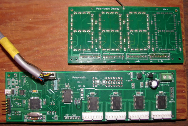
My printed Circuit Boards
The main board holds the highly-integrated processor and high-current, open-drain, protected drivers for controlling large LED displays. Communications between the boards is by serial RS485, which can be used at distances in excess of 1km. I might use the PCB for other experiments, so I put on a second RS485 channel, an extra LED driver chip, a small prototyping area, and a voltage reference and test points to use the A/D and D/A of the processor. I ended up with only one small jumper needed on the logic board; not too bad!
Microchip offers a variety of inexpensive PIC24H development tools including a free C compiler and Integrated Development Environment (IDE) which works quite well (and now supports Linux!). I used the IDE to write code in C for the Master and Remote boards, and the PICKIT 3 interface to program them and perform source level debugging. In short order I had the prototype up and running!
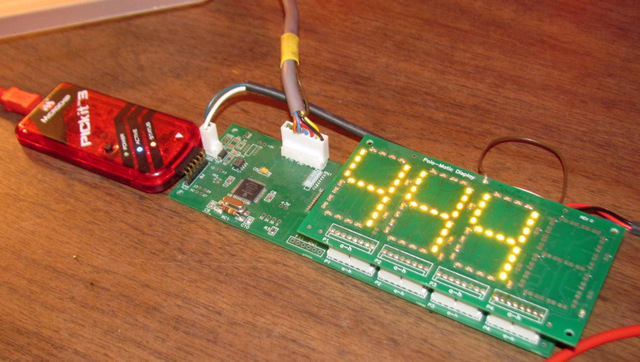
PICKIT 3 in circuit debugger in use
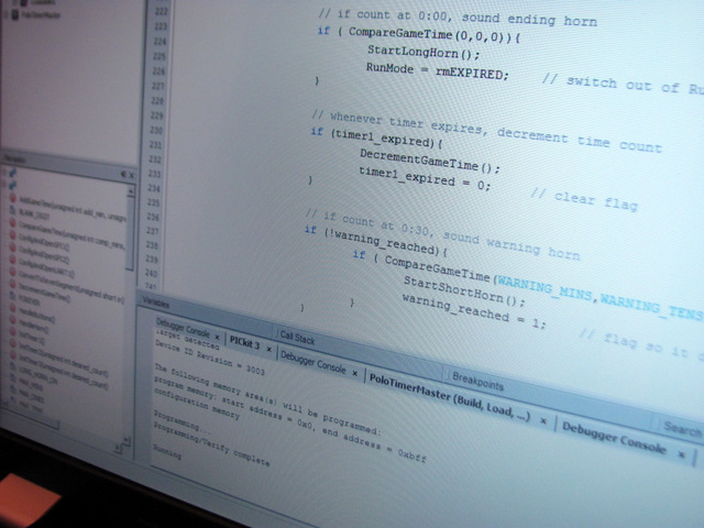
Source level debugging!
Having a full symbolic programming environment, with source level debugging, breakpoints, and single stepping, basically for free, is rather mind boggling. A few years ago those were things I only dreamed of having while working for wealthy corporations!
On the back of the outdoor display unit, the Remote board drives large LED digits. I tried to make the outdoor unit quite rugged and relatively weather-proof. The outdoor unit holds the power supplies (and car horns for announcing end of period). Only one cable to the control panel is needed.

Remote unit logic board
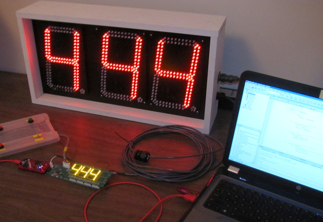
My original user interface panel had an off-the-shelf 2″ red LED display (with serial interface), but we just couldn’t reliably see it in direct sunlight. So I designed my own display PCB using tiny high-brightness amber LEDs driven by the logic board’s driver chips. It stacks right on top of the logic board to eliminate cabling and is way brighter.
Stackable LED board
This winter I hope to change the outdoor unit LED digits to high-brightness green LEDs. We found the red just didn’t have great visibility in the glare of a sunny polo field. I asked the vendor about making the displays with brighter LEDs (they are made in Thailand!), but they weren’t interested, so I will have to change them myself. It’s going to take a lot of desoldering, but I think it will be worth it. I also have a rugged “plastic lumber” enclosure in the works for the user interface.
Hopefully the unit will be ready for matches in the spring of 2015!
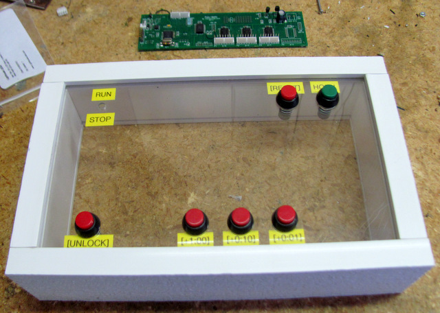
User Interface Housing